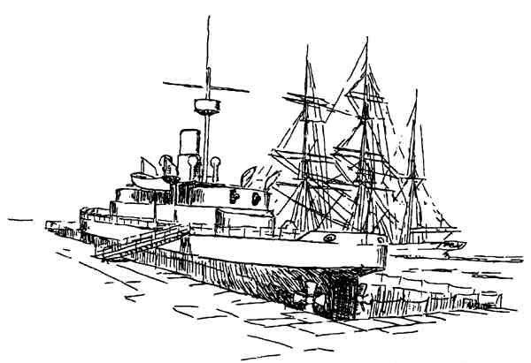
One of the earliest steam driven ships in Australian Naval service was HMVS CERBERUS: she now lies part submerged off Sandringham and serves as a breakwater.
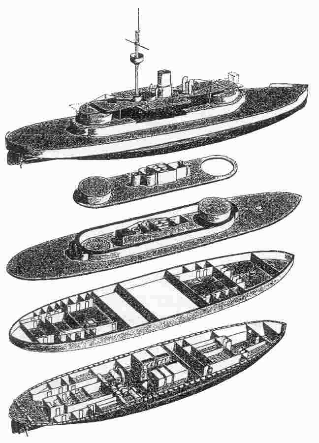
CERBERUS was the first of a line of Breastwork Monitors built in the U.K. in the 1870's and her design concepts were followed for major ironclad warships until the end of the nineteenth century: these concepts aimed to provide heavy seaborne fire power against shore targets but yet to present the minimum of target to enemy gunners. When on passage these ships would steam at a relatively light condition with maybe six feet of freeboard. On arrival at the bombardment area ballast tanks would be flooded until only a meer couple of feet of freeboard remained. Such target area as was then presented was protected by heavy armour on the ship's side, around the turret breastwork and on the turrets themselves.
CERBERUS' main armament was four ten inch bore muzzle loaded rifled guns each weighing eighteen tons, two in each turret. Turrets were carried on substantial rollers set between roller paths beneath the periphery of the turrets - training was hydraulic. Indications are that most of the recoil of these guns was absorbed by a form of hydraulic(?) amortiser fitted between the sloping rails carrying the gun carriages. The remainder of recoil energy pushed the carriages up the slope until they were ultimately stopped by buffers and held in this position for reload which could now be accomplished from within the turret.
Imagination can conjure up the following drill after a round had been fired:
- number one of the gun's crew (the gunlayer) orders 'reload'.
- number three clears out burning debris from the bore of the gun with his combined sponge and rammer. The wet sponge cools the bore.
- number two and six push a bagged charge of powder into tne muzzle for three to ram home.
- number four and five lift the heavy ten inch shell into the muzzle and assist number three to ram this home.
- number two puts a wad into the muzzle which, when rammed home, will retain shell and charge at the breech end of the gun.
- numbers two and six release the carriage and, with manual operating gear, run the gun out to the firing position ('hence two six heave')
- number two now sets elevation on the gun as directed by number one (the gunlayer) while number five takes over as trainer and and calls out his orders to the training crew on the deck below.
- number two primes the touch hole with powder and reports 'gun loaded' and 'range set' to number one.
- if both guns are loaded the gunlayer then reports to the gunnery officer 'for'd (or after) turret ready.'
- when appropriate the gunnery officer will reply 'cock',
- without taking offence the gunlayer will water down this ambiguous reply to order the number two of each guns crew to 'cock your gunn'. Flintlocks will then be reported cocked and the gunlayer will report 'for'd turret guns cocked.'
- on receipt of the order 'Fire' the gunlayer, pausing as necessary until the roll of the ship aligns his optical sight with the target, will repeat the order 'Fire' to the number two crew members. Flintlocks will be triggered, guns will fire and the whole sequence will start again on the order to load.
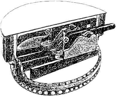
The Two Muzzle Loading Guns in their Turret
Very little is known concerning propulsion machinery, but drawings show four rectangular type boilers each with three furnaces.1 Coal stowed in bunkers around the four sides of the stoke hold was transported to the firing plates in trucks running in a tramway with turntables at the corners and at the turn off to the plates. Steam was generated at 30 psi (nearly two bar)
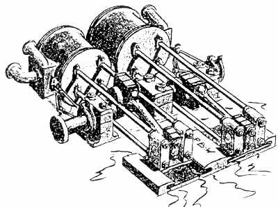
Maudslay's Return Rod Connecting Engines
The four cast iron blades of each of the twin propellers were bolted to their propeller hubs. The propeller shafts were each supported by three plumber blocks and were driven by double acting two cylinder simple engines. These horizontal engines were Maudsley's return connecting rod design with a relatively short two foot six inch stroke and large three foot six bore. Each piston drove its crosshead through either two or four connecting rods which were disposed above and below the crankshaft on each side of the crankwebs. It is presumed that crosshead mounting slippers ran in guides on the engine bed plates. From the crosshead pins the connecting rods led back to the crankpin journals thereby forming a relatively short engine but still with reasonably long connecting rods.
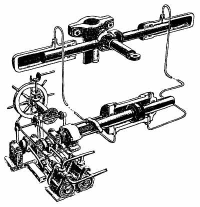
The steam steering gear had features in the tiller flat such as the rams and their sliding sleeve connection with the tiller which have survived to the present day. The mechanism amidships at the steam end of the system, while interesting in concept, has long been superceded. It is believed to have worked as follows: when the helm was moved, either from the normal conning position or locally by the wheel in the steering engine space, the engine eccentric shaft was turned causing the engine pistons and crankshaft to move in time with, and in the direction of, the application of the helm. The crankshaft turned a multi start sqaure threaded screw engaging with a nut within a hollow piston rod. The piston was thus moved within its oil filled cylinder and would discharge oil into one or other of the rams in the tiller flat; the rudder would thus be moved.
HMVS CERBERUS - DAMAGE CONTROL HQ WALL CHART
From smudges on the drawings to hand the only other outside steam engine to be found is the two cylinder engine slung from the deckhead of the forward hold which drove the cable gypsy on the forecastle. Carried on the gypsy shaft in the forward messdeck was a capstan which presumably could be clutched in if steam engine failed: in this case it is presumed that the messdeck would be cleared of tables, capstan bars rigged and the capstan's crew invited to heave around on the capstan in order to weigh anchor by hand. Other hydraulic features included numerous pumps operated by multiple hand cranks on the mess decks. These would cope not only with bilge water but would also pump out ballast tanks.
Auxillary steam machinery within machinery spaces included a circulating pump for condensers, a pump for nebulous duties - perhaps firemain and a 'wind machine' to push a good draught of air into the stokehold.
Hull outer plating was of half inch 'LOWMOOR' iron, much of which has withstood over one hundred and eleven years of exposure. The ship's side armoured belt extended six feet down from the upper deck level and was mounted with an intermediate wooden skin aganst the hull plating. The armour on the breastwork and on the turrets was similarly mounted. No side scuttles penetrated this armour and such daylight as reached the lower deck or breastwork space was through hatches or skylights.
Extensions to the forward and after ends of the Flying deck 3 provided additional platforms on which a small charthouse could be carried and against which boat davits could be fitted. These extensions would be unrigged and left ashore if the ship expected to go into action or carry out gunnery exercises.
Fired by nostalgia, no doubt generated by far deeper insight into the ship than this article can muster, the City of Sandringham has raised a proposal to consider refloating CERBERUS and towing it to a local exhibition area for partial restoration. The ship would subsequently be displayed near the old time square rigger POLLY WOODSIDE.
1 Since this publication was written information has come to light indicating that there were originally three large boilers with 3 furnaces each. There were also 2 auxillary boilers with two furnaces each. The drawing on page 4 has been altered to reflect this new information.
2 It is also now known that the Steam Steering Gear was designed by the Victorian Government Engineer, Alexander Wilson
3 The flying deck was shortened in 1888. The removable "extensions to the forward and after ends of the flying deck" refered to in the text did not ever exist.